Everything here was considered correct at the time; I may
correct myself as I proceed through this Design Document
I am about to begin placing all my assets from the past year
into engine. From what I have heard already this is a near impossible task.
What I will have to do
- Alter my assets so that they conform to UDK, this may include, changing, geometry, Unwrap and texture sheets.
- Alter texture sheets due to using the 3DS Max in house, spec and normal bump sliders.
- Rescale these assets
- Set to 0.00 on the grid
- Reset pivot
- Rest X-Form
- Import these assets
- Import their Texture sheets
- Get the texture sheets working. Alphas and tiling.
- Use light maps?
- Use collision maps? Boxes? Geometry???
- Do this for every asset.
To Do
- Read all supplied, briefs and tutorials. Get a slightly better understanding of what I have to do.
- Youtube, google and ask friends untill the job is done.
“Following” the Tutorial (none of the below is in the
tutorial)
In 3DS Max
- Do not prefix your mesh SM_. Don’t use a prefix.
- Do prefix the collision mesh UCX_ but give it the exact name as the main mesh.
- Do not export from 3DS Max in ASE format, Export in FBX
- This completely changes the export menu that then comes up. Then only check smoothing groups, split per-vertex normal and preserve edge orientation. Then go into the animation, cameras, lights and embed media tabs and uncheck the boxes in them, then you can export.
In UDK
When
looking at the initial import panel, expand Static mesh, then click on advance
and then make shore explicit normal is ticked.
Following the above points in conjunction with the tutorial
has gotten the collision mesh working. But doing this seems to do something
with the smoothing groups as apparently now there aren’t any, or so UDK warns.
The problem here it suggests is ticking split per-vertex normal. Although the
smoothing groups actually appear to be working.
Also the Alphas don’t work in engine. In the material Editor
changing the Blend type, to Blend Translucent fixes that. Hmmmmm this isn’t actually an alpha, this is
simply making this hole material clear, which is what I wanted for the glass
I’m working on, but for actual alphas this will not do.
Also in the material editor you have to tick 2-sided in
order to see both sides of a plane.
I’ve gone through this hole process for the Telephone Box
about a dozen times now. Every time I made a mistake I would close UDK, without
saving and re open it. I’m trying to make this process second nature. I can now
go through this without referring to the tutorial.
Current Problems
- I still don’t know how to get alphas to work
- My scaling is a bit off, I did briefly import the van and it was a bit small. Which is odd considering I actually typed in the exacts dimension of the van in Max. I don’t believe it currently sits at 1.97 meters high. The Telephone Box is slightly short also.
- Still don’t know what a light map is.
- Still don’t know how to save a package.
Further Progress
You save by simply right clicking on a package and then
selecting save. Where I have been going wrong is that I have been, trying to
select a file type. If you just leave it blank UDK select the correct one for
simply saving out into a folder. You can then reload this package via “open an
external package”.
Although when I then drop the phone box into the environment
I get this warning.
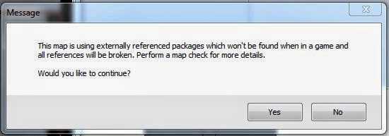
This seems to be happening because I’ve been saving my work,
in a folder in my pictures (with everything from the whole year, organised to
hell and back). UDK can only really understand things that are stored in its
default contents folder, which is in its program files. Also if you have more
than one version of UDK on your computer this can also confuse UDK even when
you have saved into the correct contents folder. As I have downloaded the
version of UDK with all the unreal Assets in it and the blank version. I am now
going to have to delete both these versions of UDK and re download them.
I have done this, and re-made the telephone box, I can now
save the Telephone Box out to the contents folder. Now that I have done this it
seems that you don’t have to re-load this asset, it’s simply always there in
the contents which is instantly accessible via the Contents Browser. Also when
you first click on it here, it looks like it’s lost all of its content, but if
you right click on it and then click fully load it brings up all the content
within this package.
Light Maps
This is the creation of a second UV layout in Max, Which
then UDK uses to establish what surfaces are to be affected by light
separately.
This is done by adding another UV channel in Max. You then
click move from the two options that then come up. This then brings up all your
previous unwraps from the first channel which is your Diffuse, spec, and normal
but for all of your multi-subs on one UVW template. On this template you then
have to lay out every single plane. When doing this if you go back to the first
channel, you then have to click abandon instead of move, when prompted. Once
you have finished laying out all the UV’s you can then export this file just as
before and open it up in UDK just as before. UDK by default uses the second UV
channel for light map information.
When I first did this for the Telephone box due to a
misleading tutorial I believed that the industry standard was to use light maps
that were 32×32. And this is what I did. Now that I have done this and found it
next to impossible. I also I asked a
question on DMUGA Technical, I now realise that this is not the way to do light
maps and that it is fine to multiply up to a more reasonable size. Obviously as
always try and be as efficient as possible.
Now that I have gone through all these processes I can
now hopefully duplicate this for the remaining assets

Alphas in UDK-In the material Iditor, click on Material and
then change Blend_Opaque to Blend_Masked
Scaling in UDK-Through repeatedly Exporting meshes from 3DS
to UDK at different sizes I have worked out the character in UDK stands at
about 270cm tall. This is with the mode set so that you are actually running
about as a character, as if in game. This is not the default setting, the
default point of view sits allot higher than this. You change to a more
accurate in game height by selecting view, then world properties, and then
changing the game mode to Death Match. I actually don’t have Death Match as an
option, but selecting standard Game does give you the correct point of view.
Standard Game though does not give you a weapon. Now that I know the height of
my point of view in UDK I can now change the scale of all my meshes in 3DS
prior to export. This is done by simply changing the unit setup to cm. You can
then build a reference box that sits at 270cm tall. Then scale your assets to
the required size. Then export. When this is then imported into UDK and dropped
into the world it should be scaled correctly relatively to you and all your
other assets if all scaled the same.
I have currently placed all of my usable assets into UDK in
separate organised Packages. They are all scaled, textured and the Collision
meshes are working.
All accept the Gladiator, for some reason although I have
gone through the same process with all my meshes with the same result the
Gladiator has not worked. UDK is only recognising one Sub-Object ID. This means
that only a single texture can be applied and that it covers the entire Mesh.
Also when this abomination is dropped into the level, it isn’t visible.

I like to call him Carpet Man
I never worked out why he wasn’t visible this seemed to just
fix it self, I fixed the issue with the Multi-Sub though. This was happening
because both my Multi-Subs in 3DS were using Standard Material boxes with the
same name. Even though they were named correctly within the Muti-Sub, and were
two different Sub-Objects, UDK still recognised that they had the same name.
Also none of my light maps are working.

Also both of my flat mates have the exact problem, but not
on all of their meshes, and we still can’t discern why.
There is one definite fix though, this is to export the mesh
in ASE format, although I have been told that this format is obsolete, and FBX
is more appropriate.
Everyone I know with this light maps issue is using FBX.
This problem doesn’t seem to occur in ASE, so I could try using ASE, but this
would not solve the issue of not knowing how to get light maps to work when
using FBX.
Problem Solved
We have found a way of using FBX files that retain their
light maps. When exporting the file in
FBX format from 3DS, under geometry un-tick Split Per-Vertex Normals. Now you
have to change the type of FBX file, click on Advanced Options and then FBX
File Format. Change the type to ASCII and the Version to FBX 2012.
Now import the mesh into UDK as normal, the light maps for
me now work.
Current Problems
- My Gladiator currently has a line running down his chest, when I initially imported him this was not an issue. Although I managed to help a mate solve this issue by changing the Compression settings when importing a Normal Map, here you change the Compression Setting from TC_Default to TC_Normalmap. Currently when I do this to mine this does not solve the problem.
- Although my light maps are currently importing correctly, there are many issues with them. I will need to go back into them, and rerere-check for over lapping faces, as the Select Overlapping Planes tool in the UV Editor is not to be trusted apparently.
- I’ve also made a tillable road plane, but It’s extremely difficult to tile these in UDK due to the apparent lack of a Snap to Objects (or similar) movement tool in UDK. You can Tile these segments by eye but this just seems stupid, it takes time and is never truly perfect. There is always an angle where Z-Fighting is visible, even if it’s extremely slight, this just doesn’t seem like a professional way of doing this. There is a fix, although I have made a plane in 3DS-Max so I have created Geometry for this task, if I just drop the material alone into the world it textures the whole ground. If I then change the tile settings appropriately, the hole scene is now tiled. This is what I was planning to do but with a tillable plane, so the result is the same.


Trying to Solve the Problems
Road Surface
I thought that if I set the scale
of the tile to that of the grid in UDK, then when using the Snap to Grid
function, it might then tile correctly. I’ve read that UDK uses are 1:1 scaling
system, 1cm is relative to 1 UDK unit, also that the Grid is using dimensions
that sit at multiples of 2. So setting
the dimensions of the Tile to 512 might fix the problem. Nope, sill snap to
grid leaves a gap between two tiles.
Gladiator
I’ve re-unrapped the light map.
I’m hoping that the line down the Gladiators centre was caused by this being
the edge of two different planes on a light map, bot showing slightly different
information. So I’ve altered it so that the light map seams are now on the side
of the Gladiator. This has not solved the problem.
Transit
I’ve also tidied up the light map
for the Transit, hoping that this might sort out the blotchiness; I’ve also put
the light map up to 2048 in UDK. The light map is better but there are still
large patches of random dark shadow where there shouldn’t be.
I’ve unwrapped it again but this
time with greater gaps between all the planes. Again this has not solved the
issue.
Mean While
I have created some double yellow
lines including a corner. They’re both from the same 3ds file save apart from
one had a Bend Modifier applied to it and has a different name. The bend for
some reason in UDK warns me that it doesn’t have a collision mesh, and the
straight bity doesn’t, although they were both made the same and both don’t
have collision meshes. I don’t think collision meshes are necessary for these
because they will always be sat on top of a Road which will have a collision
mesh.

Here I think I accidently grabbed the Material instead of
the mesh, when dropping it into the world.
As you can see I fixed it.

Doing a design document was not part of this project this is
something which I have done for myself. During this project I had to learn a whole
new program, this blog was used to straighten out every thought I was having
during the process. This also served as a way of storing new information.
During this project I recalled back to this document to remember how to do various
tasks. This is just me leaning something, and then taking that information and reiterating
it so that I will then hopefully remember it.


No comments:
Post a Comment